6SJ7 - Vacuum Tubes, Humor & Technology
Pentodes were introduced to eliminate the restriction on plate voltage swing
of the tetrode, by getting rid of the dip. A new third grid between the screen
grid and the plate, the suppressor, was held at cathode potential and repelled
secondary electrons back into the plate, as well as making the electron division
independent of plate voltage. This made pentodes useful for audio and power
amplifiers in general as well as for RF amplifiers. The screen grid, at signal
ground, reduced the grid-plate or Miller capacitance to very low values, less
than 1 pF, as for tetrodes. The consequent reduction in negative feedback at
high frequencies made RF amplification possible without hard-to-adjust
neutralizing circuits. Therefore, pentodes were always found as RF and IF
amplifiers in radio receivers. These were voltage amplifiers, and of two kinds:
sharp cutoff and remote cutoff. The remote cutoff pentode had a control grid of
uneven spacing, so that when the bias was large, the transconductance of the
tube became small, limiting the gain so that the amplifier would not be
overdriven and produce distortion. Typical RF pentodes are the octal 6SJ7
(sharp) and 6SK7 (remote), or the miniature 6AU6 (sharp) and 6BA6 (remote).
Usual plate currents were 10 mA or less.
It was also found that pentodes, like tetrodes, made excellent voltage
amplifiers, because of the increased plate resistance. A pentode acted like a
current source instead of a voltage source. This put a premium on high
transconductance, which made large gain possible in a single stage. Gains of 40
or 50 are quite practical in a pentode voltage amplifier, in contrast with gains
of around 15 for a medium-mu triode amplifier. On the other hand, the gain of a
stage now depended sensitively on the load resistance; if this varied with
frequency, as for a loudspeaker, so did the gain. This was only a disadvantage
in final power amplifiers, of course. Sharp-cutoff pentodes were widely used as
audio amplifiers.
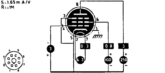
 The circuit for measuring pentode characteristics is shown at the left. The tube
used as the example is the 6SJ7, but any sharp-cutoff pentode will do, such as
the miniature 6AU6. It makes things very easy if you have four DMM's for the
various measurements. The screen supply can be fixed-voltage. I used 105 V from
a VR tube at first, later the all-in-one supply described above, which proved
very convenient. The plate supply should be variable, as well as the grid bias.
When screen and plate voltages are first applied, the grid bias should be set to
some negative value to avoid surprise. The cutoff bias can be estimated at about
1.5 times the screen voltage divided by the screen amplification factor (take as
10 if you do not know it beforehand). Vacuum tubes are much more rugged than
transistors, and a momentary oversight will not usually result in disaster. The
suppressor grid of a pentode is always connected to the cathode, and is often
not even brought outside the envelope, but is connected internally to the
cathode.
The circuit for measuring pentode characteristics is shown at the left. The tube
used as the example is the 6SJ7, but any sharp-cutoff pentode will do, such as
the miniature 6AU6. It makes things very easy if you have four DMM's for the
various measurements. The screen supply can be fixed-voltage. I used 105 V from
a VR tube at first, later the all-in-one supply described above, which proved
very convenient. The plate supply should be variable, as well as the grid bias.
When screen and plate voltages are first applied, the grid bias should be set to
some negative value to avoid surprise. The cutoff bias can be estimated at about
1.5 times the screen voltage divided by the screen amplification factor (take as
10 if you do not know it beforehand). Vacuum tubes are much more rugged than
transistors, and a momentary oversight will not usually result in disaster. The
suppressor grid of a pentode is always connected to the cathode, and is often
not even brought outside the envelope, but is connected internally to the
cathode.
The first thing to do is probably to measure the screen or triode-connection
characteristics. To do this, connect the screen and plate together and measure
the total current with a single DMM. Set the grid bias, and then measure the
total current as a function of voltage over the range available to you. Repeat
for several values of the grid bias, so you obtain a family of curves like the
plate characteristics of a triode. From these curves, estimate the amplification
factor, plate resistance and transconductance, just as for a triode. Now connect
the plate and screen to their separate supplies, and run plate characteristics
for a fixed screen voltage. In this case, the cathode current will be about
constant, and will divide between the screen and plate. Determine the ratio of
division at various plate voltages.
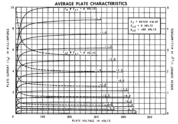
For the 6SJ7, I found gm = 2.56 mS, which is quite high for this
tube. With 75 V on the screen, cutoff was at about -5 V on G1, and the screen
resistance rg2 was about 8200Ω. I also found that the screen current
is about 0.3 of the plate current, roughly independently of voltage, if the
plate and screen are at about the same voltage. The screen takes a rather large
proportion of the cathode current in such tubes, but this is not deleterious
since the total current is small.
The suppressor grid of the 6SJ7 is brought out to a separate pin, and is
normally connected to the cathode at the socket. By testing the tube with the
suppressor grid connected to the plate, you can see that the suppressor grid is
a bit more complicated in action than usually thought. It makes little
difference whether the grid is connected to plate or screen, showing that the
current intercepted by it is small, and does not affect the results. When the
plate voltage is higher than the screen voltage, nearly all the current goes to
the plate. As the plate voltage is decreased below the screen voltage, the
screen current rapidly rises until it is about equal to the plate current. This
rapid variation in the plate current would be quite annoying. The suppressor
grid, when connected to the cathode, does indeed send secondary electrons back
to the plate, but it is evident that it also affects the distribution of the
cathode current between plate and screen, and the effect of secondary electrons
is not as great as it may seem. With the suppressor grid connected to the
cathode, as is the usual case, the plate and screen currents are both
practically constant, with the screen taking about 20%. One could use the
suppressor grid to change the plate current, and, in fact, this is done in the
pentagrid converter, which has a different structure and a special grid for this
purpose, as we shall see below.
 A pentode voltage amplifier using a 6SJ7 is shown at the left. The AC gain of
this amplifier is close to gm = 1.6 mS times 68.8k, or -110. It won't
be quite this high with a 90V B+, but will still give a lot more gain than the
triode amplifier. My 6SJ7 gave a gain of -60 at Vbb = 90 V, and Vp
was 27.2 V, showing that the plate current, 0.63 mA, should be reduced a little
to raise the plate to about 45 V. The 6SJ7 tested was very close to
specifications, despite its age.
A pentode voltage amplifier using a 6SJ7 is shown at the left. The AC gain of
this amplifier is close to gm = 1.6 mS times 68.8k, or -110. It won't
be quite this high with a 90V B+, but will still give a lot more gain than the
triode amplifier. My 6SJ7 gave a gain of -60 at Vbb = 90 V, and Vp
was 27.2 V, showing that the plate current, 0.63 mA, should be reduced a little
to raise the plate to about 45 V. The 6SJ7 tested was very close to
specifications, despite its age.
A good example of the remote-cutoff pentode is the type 39/44, which uses a
5-pin base and a grid cap, so it is interesting to experiment with. You could
also use a type 78 with a six-pin socket and grid cap, or the identical 6K7 with
an octal base, or the later 6SK7. All these tubes should give equivalent
results. They were very popular for rf and if amplifiers. Their feature, as we
have mentioned, is that the transconductance, and so the gain, could be varied
by changing the grid bias. The 39/44 has a maximum plate voltage of 250V, and a
maximum screen voltage of 90V. The heater is pins 1-5, taking 0.3A at 6.3V. The
plate is pin 2, the screen pin 3, the cathode pin 4, and the control grid is
connected to the cap on top. In lieu of a proper grid connector, I use a short
piece of 3/8" I.D. lucite rod to fasten the grid connection.
 If you run characteristics of the 39/44, using 90V on the screen, the transfer
characteristic looks like the figure at the right. Above about 4 mA plate
current, the transconductance is about 1.0 mS, and below about 2 mA plate
current, it is about 0.2 mS. It varies smoothly, of course, so the
characteristic is curved. This means that there will be distortion for large
grid swings, but the tube is not used in this way, like a power pentode would
be. I actually found rather linear variation for small and large plate currents.
The plate resistance is about 1 MΩ, so the tube is a pretty good current source.
In a transistor amplifier, we can change the gain by changing the collector
current, since the transconductance is proportional to it.
If you run characteristics of the 39/44, using 90V on the screen, the transfer
characteristic looks like the figure at the right. Above about 4 mA plate
current, the transconductance is about 1.0 mS, and below about 2 mA plate
current, it is about 0.2 mS. It varies smoothly, of course, so the
characteristic is curved. This means that there will be distortion for large
grid swings, but the tube is not used in this way, like a power pentode would
be. I actually found rather linear variation for small and large plate currents.
The plate resistance is about 1 MΩ, so the tube is a pretty good current source.
In a transistor amplifier, we can change the gain by changing the collector
current, since the transconductance is proportional to it.
 The circuit at the left is closer to the way the tube was used in practice, when
the load was usually a tuned IF transformer. In place of the transformer, there
is a 10 mH rf choke. The results of the experiment may depend somewhat on what
choke is used; this one is a Digi-Key M7103, with a ferrite or powdered iron
core. Vary the frequency of the signal source to find the point of maximum gain;
in my case, it was at 269 kHz. You will probably be astonished by the gain--I
found -318! The phase shift is 180° at maximum gain, so the tube is working into
a load of about 320k. Obviously, the 10 mH coil is in parallel resonance at this
frequency. If you compare output and input with the scope, the output will lag
at a lower frequency, and lead at a higher frequency, as expected, and the
resonance has a fairly high Q. The actual coil is more or less equivalent to a
35 pF capacitance in parallel with the 10 mH. Above 269 kHz, it is a capacitor,
not an inductor!
The circuit at the left is closer to the way the tube was used in practice, when
the load was usually a tuned IF transformer. In place of the transformer, there
is a 10 mH rf choke. The results of the experiment may depend somewhat on what
choke is used; this one is a Digi-Key M7103, with a ferrite or powdered iron
core. Vary the frequency of the signal source to find the point of maximum gain;
in my case, it was at 269 kHz. You will probably be astonished by the gain--I
found -318! The phase shift is 180° at maximum gain, so the tube is working into
a load of about 320k. Obviously, the 10 mH coil is in parallel resonance at this
frequency. If you compare output and input with the scope, the output will lag
at a lower frequency, and lead at a higher frequency, as expected, and the
resonance has a fairly high Q. The actual coil is more or less equivalent to a
35 pF capacitance in parallel with the 10 mH. Above 269 kHz, it is a capacitor,
not an inductor!
In a typical Circuits or Electronics course, the 10 mH choke would be just
that, and would have an inductive reactance of about 63k at 1 MHz. Woe to the
student who would say that it would have a capacitive reactance of 4500 ohms at
this frequency, but it would have, all the same! Above 270 kHz, this choke is
more like a short circuit than a choke.
If you replace the 10 mH choke by a resistive load, you can see how the
circuit would be affected. Now there is a voltage drop in the load resistor, so
it is limited to about 33k if the plate current is 4.8 mA (obtained by a 510Ω
cathode resistor), and the gain to about -33. If you try to overcome this by
using a small plate current, say 1.6 mA (cathode resistor 4700Ω), then a larger
resistor, say 47k, could be used. However, the gain would now be only -9.4,
since the transconductance is so much lower. A remote-cutoff pentode is not
suitable for low-plate-current voltage amplifiers--a sharp-cutoff pentode should
be used instead, or even a high-mu triode. However, the remote-cutoff pentode is
just the thing for reactive or transformer-coupled loads, since these do not
reduce the plate voltage. It is very satisfying to be able to compare the
behavior and use of remote-cutoff, sharp-cutoff and power pentodes.
 An RF amplifier using a 6SK7 remote-cutoff pentode is shown at the left. You
could also use the miniature 6BD6, which is a little less expensive, or the
6-pin base type 78, the prototype for these tubes. The 6SK7-GT is very well
shielded, with a Cgp = 0.005 pF, which makes the Miller effect
negligible. Note that the grid bias can be varied. The purpose of this is to
show the variable gain of the amplifier. In a radio receiver, the grid bias is
supplied by the AVC (automatic volume control) circuit, and is the dc value of
the rectified signal at the detector (see below). The gain of this amplifier is
near -100 for zero bias, decreasing to -8 at a bias of -12V. Adjust the
frequency of the signal generator for maximum output. Since this circuit has
only one tuned circuit, there is no problem with alignment. Measure the gain of
the circuit as a function of grid bias. The decrease of gain is practically
linear up to about -8 V, but then begins to curve over rather than decreasing
abruptly to zero. If we assume an ideal linear dependence, then the output
signal is limited at the value that gives the cutoff bias. In a practical case,
the amplitude of the output varies slowly with the amplitude of the input. If
the input signal is weak, we get the full gain of the amplifier. Note that the
only components in this circuit, besides the tube, are the two air core
transformers. A practical circuit would have some other components, but this
circuit shows the principle at its simplest.
An RF amplifier using a 6SK7 remote-cutoff pentode is shown at the left. You
could also use the miniature 6BD6, which is a little less expensive, or the
6-pin base type 78, the prototype for these tubes. The 6SK7-GT is very well
shielded, with a Cgp = 0.005 pF, which makes the Miller effect
negligible. Note that the grid bias can be varied. The purpose of this is to
show the variable gain of the amplifier. In a radio receiver, the grid bias is
supplied by the AVC (automatic volume control) circuit, and is the dc value of
the rectified signal at the detector (see below). The gain of this amplifier is
near -100 for zero bias, decreasing to -8 at a bias of -12V. Adjust the
frequency of the signal generator for maximum output. Since this circuit has
only one tuned circuit, there is no problem with alignment. Measure the gain of
the circuit as a function of grid bias. The decrease of gain is practically
linear up to about -8 V, but then begins to curve over rather than decreasing
abruptly to zero. If we assume an ideal linear dependence, then the output
signal is limited at the value that gives the cutoff bias. In a practical case,
the amplitude of the output varies slowly with the amplitude of the input. If
the input signal is weak, we get the full gain of the amplifier. Note that the
only components in this circuit, besides the tube, are the two air core
transformers. A practical circuit would have some other components, but this
circuit shows the principle at its simplest.
 The sharp-cutoff pentode made the best high-gain audio voltage amplifiers. A
circuit with gains of over 100 is shown at the right. The tube is the type 77,
which uses a 6-pin base. The heater is connected to pins 1 and 6, taking 0.3A at
6.3V. I used the 77 for the fun of it, since it is not an expensive tube, the
construction is evident, and it harks back to the 1930's. The outer electrode
that you see is the external part of the screen grid, not the plate. Peek under
it to see the actual plate. The octal 6J7 has the same electrical
characteristics (except that the 77's screen voltage is 100V max.). The 6SJ7,
which we looked at above, is also very similar. The "S" meant single-ended,
since the 6SJ7 does not have a grid cap. Two sets of values for the components
are shown for this amplifier. The upper values give a gain of -164, a plate
current of 135 μA, a plate voltage of 29V, a screen voltage of 17V, and a grid
bias of -0.8V. The lower values give a gain of -117, a plate current of 262 μA,
a screen voltage of 20V, and a grid bias of -0.9V. It is necessary to have a low
plate current to permit a large plate resistor for high gain, so the screen
voltages are quite low. No load is shown for the amplifier, but it would usually
be a high-impedance grid.
The sharp-cutoff pentode made the best high-gain audio voltage amplifiers. A
circuit with gains of over 100 is shown at the right. The tube is the type 77,
which uses a 6-pin base. The heater is connected to pins 1 and 6, taking 0.3A at
6.3V. I used the 77 for the fun of it, since it is not an expensive tube, the
construction is evident, and it harks back to the 1930's. The outer electrode
that you see is the external part of the screen grid, not the plate. Peek under
it to see the actual plate. The octal 6J7 has the same electrical
characteristics (except that the 77's screen voltage is 100V max.). The 6SJ7,
which we looked at above, is also very similar. The "S" meant single-ended,
since the 6SJ7 does not have a grid cap. Two sets of values for the components
are shown for this amplifier. The upper values give a gain of -164, a plate
current of 135 μA, a plate voltage of 29V, a screen voltage of 17V, and a grid
bias of -0.8V. The lower values give a gain of -117, a plate current of 262 μA,
a screen voltage of 20V, and a grid bias of -0.9V. It is necessary to have a low
plate current to permit a large plate resistor for high gain, so the screen
voltages are quite low. No load is shown for the amplifier, but it would usually
be a high-impedance grid.
Note that an attenuator is shown at the input. This makes adjusting the
signal generator much easier. I noticed a little 60Hz hum on the output, which
is not surprising in view of the large gain, and the length of unshielded wire
going to the grid cap. When fed a square wave, the amplifier showed a rise time
of around 25 μs, and a sag of 1.0V in 4.4 ms when the amplitude was 13.4V peak
to peak. These figures agree pretty well with a measurement of the bandwidth by
varying the input frequency, which gave 35 Hz to 17 kHz.
In this circuit, we use the screen to hold down the plate current so a large
plate resistor can be used even with a modest supply voltage, while keeping the
plate voltage high enough to allow a reasonable output swing. Even with the
reduced transconductance, we can achieve good gains, considerably higher than
those possible from a triode.